Monday, October 30, 2017

A small barn for the summer house 13, internal boards.

I have been making some progress on the internal boards for the small barn.
Those were the boards that I had to shift inside as I was called to work a week earlier than anticipated.
So the first task was to shift all of them out again. I decided that I could work around the table that was inside, but I still needed to move the chairs and a bit of other stuff outside before starting the actual work.

The boards are the same type as those that were put on the sub roof. It is not a typical type of boards to use for internal paneling/boards, but it is of a much better quality than the regular type used. In Denmark the usual boards to be used would be something called "rustic boards". They are made out of the surplus Christmas trees that grew to fast so they were too large to sell. The distance between the growth rings is typical 3/8" or thereabouts, so the wood is of an exceptionally poor quality. The shape is like a tongue and groove board with the tongue something like 1/2" too long. So once the boards are mounted, there is a trench between each board. They are available in various widths and either nature, or artificially whitened, smooth or rough sawn.
But that aside - I chose the other type because I think they look better in a classic barn, and they were actually cheaper per square meter (or square foot if you like).

I mount the boards using regular nails. I know that a pneumatic nail gun is faster, but I actually like to hammer in nails, so I go for the slow and old fashioned way.

Once all the boards are mounted, I plan on putting some strips of wood in the corners and around the window sills, to cover the gaps.


Internal boards mounted.

The "famous" stack..


Saturday, October 28, 2017

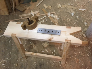
Sawbench for dowel plates

I had a plan for what I would like to build this time at home, but somehow a non-scheduled project has found it way into the workshop.

Actually it is a project that I have considered for some time: A new sawbench.
I made a sawbench something like 8 years ago, and it is one of the most used pieces of equipment I have in the shop. A thing that I have thought would be useful was if I could use a sawbench for my dowel plates. That way I didn't have to mess around on the top of the workbench, to make sure that a hole for one of the dogs was straight below the hole in the dowel plate.
Also the stretchers for the legs would be a perfect little test subject for my new chain mortiser. And with Asger and Gustav in the shop, I didn't have any room for building the staircase which meant that it was perfectly OK in my mind to start another project.

The first bench I made was made exactly to the measurements outlined in Woodworking Magazine.
This time I decided that it might not cause the world economy to collapse, if I decided to make a few alterations to the design.
So I made the top thicker, wider and a little bit longer than on the original. I stayed with the same height, and also the same angle of splay on the legs.
This time I used larch for legs and stretchers, and a piece of Sitka spruce for the top that I milled long time ago.

The tenons of the stretchers are drawbored and wedged. The top is secured with dowels that I tried to drawbore as well. I did that so that the dowels will hold the top to close to the notch in the top of the legs.
Below the top there are a couple of reinforcements glued and screwed to the legs.

I used a chisel and a router plane to make a recess for the dowel plates. I chose not to make it the same depth as the plates, because it is easier to remove the plates when there is a bit protruding through the top like it is now.
A small piece of elm was cut and planed to fit into the recess while not in use for the dowel plates.


Asger working on a gambrel roofed church.

Hot glue gun, strips of wood and some imagination is all it takes.

Glue up.

Making a recess.

Elm insert.

Blum dowel plate.

Wednesday, October 25, 2017

Haffner KKF 15 chain mortiser

Ever since I borrowed Olav's portable chain mortiser, I have been eager to get one myself. I discovered during the initial phases of the small barn build, that I really enjoy timber framing.
There aren't many used portable chain mortisers offered for sale in Denmark, and the idea of forking out $2400 for a new Festool or $4000 for  a new Mafell is out of the question. Even I have to be realistic once in a while.

I have regularly checked the various classified home pages in Denmark, and one day while looking, I spotted something on a stationary mortiser that made me take a closer look.
In addition to the lever type handle, this chain mortiser also had two smaller handles. Now those would only make sense if the machine could be used as a portable unit.
I enlarged the pictures and could see that part of it looked like aluminium castings and not cast iron. I also managed to decipher the designation of the machine which is cast into the front cover: KKF 15

A quick search and I found a page from an old catalogue that listed the features of the machine. To me the most interesting thing was that it could be used as either a wall mounted or a portable machine.

Whenever I find a machine that I would like, chances are that it is situated far from where I live, but this machine was being sold just 20 miles from our place. So I arranged with the boys that we would drive down and get it, Gustav had to be picked up at the train station after a trip to Copenhagen with his class, so first I picked him up, and then went for the machine

Originally I had intended to do a bit of haggling just as a principle, and my argument for a lower price would be that there was only one chain , and it even needed sharpening. It turned out that the chain mounted on the mortiser was in excellent condition, and besides there were two brand new chains to go along with it as well. Knowing that a new chain can easily reach 200$ on its own it seemed pointless to haggle, so I paid the guy the  $200 he was asking for the machine and he helped me load it in the back of the car.

Once home, I checked the machine, and it was in much better condition than I could have hoped for. I tested it on some pieces of scrap, and it is a joy to use.
The only problem is that even though it can be used as a portable chain mortiser, it is designed to work like that in another way than the one that I borrowed from Olav.

Olavs chain mortiser is a 100% portable machine. It is designed to work with the chain running along the grain, and it has got a clamping fixture that is perfect. Once the machine is clamped, you can slide the sword lengthwise, and make a nice long mortise that is only the thickness of the chain wide.

My machine is heavier and works across the grain when used as a hand held mortiser. That means that the width of my mortises are limited by the width of the sword and chain combined. The good thing is that You don't have to clamp the machine to the work piece. The action of the chain will ensure that it packs the fence close to the work piece all the time.
Now if I only made one size of tenons that would be OK, but I would like to be able to use the machine on different sizes of timber, so I have to figure out a way to make a clamping fixture so my machine can also work like Olavs.
A good thing about the current set up is that it is perfect for making mortises in e.g. work bench tops. Because it only requires one flat face to register to in order to make a mortise. So I don't have to invent a longer clamping fixture to span across the width of a work bench top just to make the mortises for the legs.

I guess I should make a workbench just to use the new machine..

Haffner KKF chain mortiser mounted on a stand.

Chain mechanism.

Plunged into an imaginary piece of wood.


Sunday, October 15, 2017

A small barn for the summer house 12, progress and plans.

I am getting ready to go home now, and one of the things that I always think about during the last days on board is what projects I would like to be able to work on when I get home.

By checking my blog I discovered that I hadn't made entries about the small barn that I am building at our summerhouse since late March.
That doesn't mean that I haven't been working on it., but rather that I have been too lazy to blog about it while at home.

In the early part of summer I started painting the barn, but the weather wasn't very cooperative, so basically I only got as far as to do the south gable and the underside of the roof on that gable plus a bit on the west side as well.

I also made a door and installed it. I never got around to install boards around the door though, but I can do that later since they are mainly decorative.

Last time while at home I sawed some more floor boards and sent them through the planer a couple of times, so they were the same thickness as the floor boards on the ground floor. (1.75"). Those boards were all installed on top of the beams to form an attic.
I used the same method as last time, with a handheld router making a groove in both boards, and then assembling them with a loose spline.

After completing the floor, the last two windows were installed in the gables.  Then I insulated the entire structure with 6" of rockwool. I know that a lot of people dislike insulating, but I actually enjoy it. It is very quiet, and there are quick results to be seen.
I think that the mineral wool of today is less dusty compared to what it used to be, so it doesn't bother me to do that job.
A funny thing to notice is how the sound changes when the walls are only bare insulation. It becomes very "dead".

I had purchased 882 board feet of 1" thick T&G boards that was going to be installed inside the barn, they were delivered to the site and I was just getting ready to start installing them - when the crewing coordinator of the company called me on the phone and asked if I had seen my email.
I hadn't at that time, and told her that I had checked in the morning, and there was nothing from her.

She paused and said: No, I mean the one that I sent you an hour ago. I again told her that I hadn't checked, but since she was calling she might as well tell me what it was about.
Oh, you are signing on tomorrow, and it was just the flight details, letter of guarantee etc.
???
NO WAY, am I going on board tomorrow! You sent me an email like three weeks ago, and in that email you stated that I should expect to sign on around the 19th of September (this was on Monday the 11th).
Let me see she said, and I could hear her tapping her keyboard and finding the old email. Dead silence for a couple of seconds. Oh yes, I can see that. But that was a mistake. So you are still going out tomorrow!
I tried to explain that I was not impressed with the level of planning, She started explaining that the agent in Guinea had been advised about my coming, and a helicopter trip had been arranged too etc. I then managed to ask in a polite way if I at least had an afternoon flight from Denmark. But nope - My plane was scheduled to leave from Aalborg at 06:00, t
So I had 15 hours left.
I told her that if that was the case, I didn't have any time left for chit chatting, and hung up.

I took a quick look around and started shifting all the boards into the barn so they would be protected from the weather. Cleared up the place and drove home with the surplus of insulation. Emptied the trailer for insulation and stacked it in the large barn at home. Emptied the car for tools, cleared up the mess at home (which I usually do quietly and calmly the last couple of days before leaving).
Ate some supper and packed my bags with the small toolchest and arranged for a taxi to pick me up in the middle of the night. I was still not impressed, but things such as these are the downside of being a seaman.

BUT now I am soon on my way home, and I hope to be able to install all those boards so the interior of the barn will be completed.
I have considered painting the interior white, I guess it will never be easier than when the structure is empty, plus I think that it will look good.

Another project that I have been looking forward to in a long time is to make a staircase for getting up to the attic of the barn.
I guess that a lot of people have a hard time understanding that you can look forward to such a project, but I hope that those reading this post will understand that feeling.
My plan is to make a fairly simple staircase. It will also be rather steep because I don't want it to take up too much room inside. A staircase to me represents one of those projects that are just in the borderland between carpentry and joinery. Large dimensions of stock and still the joints have to be laid out and executed with a lot of care. Yup, that is definitely going to be a rewarding project.

Depending on if the weather will be nice, which it probably won't, I could also continue with some painting outside, and perhaps mount the framing boards around the door and the window in the gables. I could also do the electrical wiring so the inside will be completed, but let's see how it all goes.


Painted end of the barn, working on a floor board.


Thursday, October 12, 2017

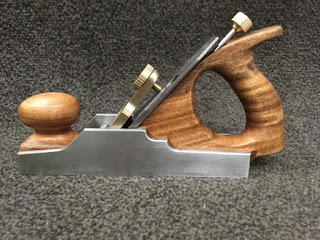
Making an infill plane from scratch 15, project completed.

Yesterday I managed to complete the Norris style adjuster and mount it. I never got around to write a blog post about it, since it was getting a bit late.

Today I realized that I couldn't really put it off any longer. There wasn't much work left to do on the plane save for sharpening the blade and make sure that it was seated well on the bed (frog). Flattening the sole and sanding everything once again.

I silver soldered the threaded part to the adjuster base, so it is not possible to do any lateral adjustment with this adjuster, only depth adjustment.
A recess was made in the front of the rear tote, by first drilling a series of holes and later chiseling the waste out. I painted the back of the base with a whiteboard marker, and I could see where it had rubbed off, that there was a high spot. The same method was later used to check and adjust the seating of the blade.
The rod with the adjustment screw could have been a bit longer, but I guess that you don't adjust such a plane all the time, and I prefer that the adjustment screw is not protruding too much form the plane.

It took a bit of fiddling to find the best initial position for the retaining ring and the threaded rod, so everything worked fine at maximum and minimum depth adjustment.

Eventually I had to file a bit more from the underside of the lever cap, to be able to slide it under the fulcrum pivotal rod (it has probably got some other name).
This caused the lever cap screw to be just in the shortest range. So I think that I will make a new screw with a 1/8" longer threaded portion.

Today I sharpened the blade and after doing that I inserted it in the plane and tightened the lever cap screw. With the blade in place and the screw tightened, I then started to flatten the sole of the plane.
The idea of doing this while the blade is in the plane and in tension is, that it could potentially distort the sole of the plane a bit, and therefore it is best to flatten while everything is as close to working conditions as possible.
I also took the time to mark the bed with MMXVII for sake of good order.

Our lapping plate is new, but still I am not convinced that it is 100% flat and true. But I guess it is good enough for a home made infill plane. And besides it is what I have.

After some more sanding I treated the wood with some olive oil. I guess that it will slowly be absorbed by the wood, and then when I get home I can give it some paste was or some linseed oil as I have originally planned.

I tested the plane to see if it would work, and it actually did. I was able to plane a small piece of Bubinga both ways. It wasn't the most dramatic grain run out, but it did its job perfect with the grain and against it.

Conclusion of the project:
This project required a lot of metal work and comparatively little woodwork. There was much more filing and sanding compared to my usual projects.
There were a few difficulties that arose during the course of the build, such as less than ideally positioned holes etc.
The Norris style adjuster is a cool feature, but I tend to think that hammer adjustment would have been better. It could easily just be my adjuster that isn't the best - but now it sits there. If it ever acts up or seizes to work, then I can always remove it and either fill out the gap left behind, or just leave it as it is.
I personally think that the plane came out all right. There are a few places that still has got some minor scratches, but it was meant to be a tool, not a sanding contest.
My favourite part of the plane is the front tote where it blends in with the sole. And the lever cap with the massive number C954 cast into the front.
If I had been at home I doubt that I would have persevered during such a project, but out here it is more a matter of doing something to keep myself busy in my spare time.
I am not sure that it works any better than a regular Stanley, but it looks better in my opinion, and besides, I think it is the only infill plane in the world that was made on board a ship.


Infill smoother, steel and Bubinga.

Finished with olive oil.

Lever cap from aluminium bronze C954


Test shaving in Bubinga.

Parts for the Norris adjuster.

Completed Norris adjuster.

Making a recess for the adjuster.

2017


Monday, October 9, 2017

Making an infill plane from scratch 14, depth adjuster.

My original plan was to make a Norris style adjuster for the depth adjustment of the blade. But after completing the rear tote, I discovered that on account of me making the handle as small and delicate as possible, I had also made it difficult to fit a regular Norris adjuster to the plane.

I have toyed with a couple of alternatives:
1) No depth adjustment mechanism, just the tried and trusted plane adjusting hammer.
2) Inventing a new type of depth adjuster.

Ref 1) This would enable me to just move forward and have the plane done in a relatively short time, but I would also risk becoming the laughing stock of the woodworking blogosphere, since I have earlier in this series mentioned that I was going to make a depth adjuster.
A positive thing would be that there is very little risk of messing up the plane.

Ref 2) I have sketched a couple of ideas, and even went as far as to begin work on the most promising of those models.
The best design sported a worm gear giving an accuracy of roughly 1/1000" for one full revolution of the adjustment screw.


Today I had to make up my mind about which route I wanted to take.
I looked critically at the screw holding the chip breaker, since that one was fairly large,and in turn that was causing the problem of an even larger retaining ring to move the blade assembly back and forth.
Very unlike my usual behavior, I decided that it might still be easier to turn a new screw for the chip breaker, and then go ahead with a regular Norris adjuster, instead of risking to mess up the entire plane in an attempt to make a supe fine adjustment mechanism.
So that ended up being the outcome.

My Norris style adjuster will not be used for lateral adjustment, since the rear tote is fairly thin on the top. So I will need a hammer to adjust it laterally anyway. But the depth adjustment will hopefully work.

The new design depth adjuster would have the depth adjustment screw going out the left side of the rear tote. This finger screw would activate a worm gear with a ratio of 30:1.
The worm gear would then drive a threaded rod with a retaining ring on it (just like a regular Norris adjuster). The threaded rod was meant to have a pitch of 1mm/revolution (M6) A bit finer than 1/4" UNC. (Maybe it is equivalent to UNF?)
So the math of the adjuster looks like this:
1 revolution of the finger screw = 1/30 round of the worm gear = 1/30 of 1 mm = 0,03 mm (1.2 thou)

Maybe I should try to make an adjuster like that one day, just for the fun of it.

Blade and Norris style pieces mounted.
Worm gear experiments above the blade.


Saturday, October 7, 2017

Making an infill plane from scratch 13, lever cap.

Yesterday I spent a couple of hours just filing the front of the mouth so that it would allow the blade to protrude. I also started chamfering all the edges of the sides. These seemingly small tasks actually take quite a long time.

Today I decided to start on the lever cap.
I have had an eye on an old butterfly valve for some time now, because it would give some great material for this part of the project.
The valve is a 12" valve that used to be mounted on the ballast system of the ship. It was replaced during the dry docking, because the rubber seating had developed a crack that caused the valve to no longer hold tight.
Not so many years ago it was custom to change the rubber insert in those valves, and it can still be done on some types yet. But this valve is of a type where the rubber is glued to the body, so it can't be repaired. It can however be used for a custom lever cap.

The disc is made out of aluminium bronze, which is sea water resistant. It is also a different colour than the steel that I have used in the build, so it should give a bit of visual interest once it is complete.

I used an angle grinder to cut out a piece I deemed suitable. I deliberately included a cast stamp saying C954. I have no idea what it means, but I thought it looked good.
After getting the piece free from the valve disc, it was again back to a lot of filing.
I have managed to position the holes for the cap iron in a way that it would look bad if it was mounted with screws in the side. So instead I am going to install a rod in those holes, and slide the lever cap below this rod, and capture it in a semicircular depression.

After drilling a hole for the cap screw and making a thread in the hole, I again used the angle grinder to remove some more material. I did this after the drilling and tapping, because it is so much easier to clamp a squarish piece in the vice compared to an odd shape.

In the beginning I considered leaving the entire surface as it came from the valve i.e. as a coarse casting, but in the end I decided that it would look like I had skipped a step or two, and I started filing the surface to get it nice and smooth.


The current state of the project, still some way to go.

Butterfly valve, empty can is for giving an idea of the size.

No one will notice that there's a piece missing.

Started to file the surface.


Drilled and tapped, but not finished yet.

Wednesday, October 4, 2017

Making an infill plane from scratch 12, riveting the sides.

Much to my surprise the marshmallow glue seemingly did its job. So technically both infill pieces were now ready to be mounted in body of the plane.
I positioned them and clamped a set of pliers on the sides to ensure that nothing moved during the drilling of the holes.
At first I drilled a new set of holes instead of those that I plugged the other day. After that all the existing holes were bored in the infills as well.

My original plan was to insert some small tubes to function as distance pieces. I had laid my eyes on a piece of stainless steel pipe, but I had to give up the plan because the hole was too large by 1 mm in diameter (3/64") compared to the rivets that I was going to use.
So a quick change of plans resulting in that I assembled the plane without any distance pieces.

The rivets are actually short lengths of round iron bar of 1/4" diameter (6 mm). Those were sanded first to remove the black crust, and one end sharpened just a bit, to make sure that it would engage the hole on the opposite side of the body.
The rivets were driven through and I started peening the metal.
After doing one rivet on one side, I flipped the plane over and completed the other side of that rivet.

The riveting disturbed the look of the sides a bit, I guess that the wood compacted a bit, and the sides naturally followed along. So the bottom of the planes doesn't look quite as nice as it did in the beginning. But the overall feeling is rock solid.

Smoothing the sides again to level out the rivets took some time. Again this is where a belt sander would come in handy, but a file can also do the job if you have a little bit of patience.

A nice trick when filing metal is to pack the file with chalk. This helps to prevent chips to get stuck in the file and make a major scratch in the surface on the next stroke.
You basically just take some writing chalk and rub it onto the file before using it.
It really helps a lot. Especially if you work in softer metals like brass, copper or aluminium but for steel or iron it also helps. These metals aren't as prone to clog the file, but any bit helps to make a nice surface.

The parts ready for riveting.

File packed with chalk.

Almost done with one side.

Body and infills assembled.

Tuesday, October 3, 2017

Making an infill plane from scratch 11, rear tote and infill assembly.

After a lot of sanding, the rear tote seemed OK to me. And it was time to tackle the job of getting it mounted in the rear infill.
I drew some lines to work out from, sawed on the correct side of them with my small Japanese pullsaw, and got busy using the chisel to mortise out all the wood.
This part of the project also took quite some time, but in the end I had a nice snug fit of the rear tote.
The front transition could have been better, but since it will be covered by the blade 99% of the time, I decided that I would stick with the result.

A nice epoxy glue would have been my preferred medium if I had been at home, or a good wood glue a second choice.
Out here the only glue we have it some superglue and some too old winter grade glue where most of the solvents have vaporized over time, leaving the glue with a consistency like marshmallow.

I chose the marshmallow glue, because I have never really liked superglue or cyanoacrylate that much.
I might end up regretting it, but I figure that if everything else fails, I can still pour down a bit of superglue into the glue crack.

Clamping the assembly after gluing wasn't very easy. but I managed to secure it after a couple of attempts.

I believe that this glue has passed its prime.

Clamping arrangement of infill and tote.

Monday, October 2, 2017

Making an infill plane from scratch 10, rear tote.

My original plan called for a closed rear tote. During this project I have searched the Internet a lot, looking at all kinds of pictures of infill planes and their handles. I suppose that I could design my own, but one search (I think it "closed rear tote plane") revealed a picture of a classic closed rear tote from an old jointer plane. The good thing was that once I visited the homepage, I found that there was even a pdf of a full sized handle.
I downloaded the pdf and intend to use it as a muster for my tote. I will need to make some alterations to the front to get it to blend in with the rest of the plane, but it greatly help to have a starting point.

Now if I could just hope to make a handle that looks 1/10th as good as those handles that Pedder turns out.

An interesting thing about the closed rear tote is that it is described as being non symmetrical in the aft most part, where the palm of your hand will push your plane. Tee idea behind this is supposedly that it will make the plane more comfortable to use for someone who is right handed compared to a symmetrical tote. On the other hand it will make the plane more of a pain to use for anyone who is left handed.
At first I was  a bit undecided if I should go with symmetrical or asymmetrical. I was afraid that if I made it asymmetrical, most people would probably think that I did a crappy job in shaping the rear part of the tote.
But once I started I decided that I could always something else that was symmetrical, and this project is about making a plane that will be a joy to use, so I ended up doing it the way it was suggested.

I sawed out a piece of wood and tried to flatten it a bit with my plane, in order to get it close to the thickness I wanted (1" 1/16).
There was a lot of tear out, and in the end I had to traverse it with the scrub plane in order to get it to look reasonably OK.

The outline of the handle was traced onto the wood, and I drilled  a series of holes to remove the hole for the fingers, and also in the upper curve just beneath the end of the tote.
The trusty hacksaw helped removing the rest of the wood.
Since I haven't got a rasp, I needed to figure out another way to remove a lot of wood with a bit of precision, and at a decent speed.

My solution was to clamp the handle to a block of wood that was held in the vice, and then using the 1/4" chisel removing small chips along the edges. This method worked way better than I had expected. It was fast, efficient, fun and the handle very quickly took on the desired shape.

There is still a lot of work that needs to be done with a file and with sandpaper, but at least I got the job started out in a good way.

A thing that didn't turn out very well was the placement of the holes that I drilled back in post No 5 in this series. The upper hole for the rear infill was placed in a way that it just missed the surface of the bed for the blade by 1/16" or so. Since my plane is to use bushings inside the wood it meant that the bushing would protrude on the bed of the blade which would effectively ruing the plane.
That left me with two options, making a new rear infill with a bed angle of 70 degrees or so, or trying to stuff the holes.
I went for the stuffing job.

I used some sort of tapered reamer/router bit that I found in order to flare out the holes on the inside of the sole.
The real mistake happened when I tried to use the same bit in the drill press. It caught the hole and dug itself heavily into the metal before I manged to turn of the power.
So instead of a nice lightly flared symmetrical hole, I had a much too large asymmetrical ugly flared hole.
To make matters even worse, I started out by riveting the nice hole in the other side. That went really well, but it left me with a much more difficult job to peen the inside of the rivet in the ugly hole. Since I could no longer get the drift pin in from the other side (as I had just closed that hole with a rivet).
I hammered til I was afraid that I'd might hit the side itself, and then I stopped. The heads of the rivets on the inside were filed level, so that I could insert the rear infill again.
The outside was left after a couple of strokes of a file, because I figured that it was better to file all the rivets once I have assembled the entire plane.
At some point I need to drill another set of holes in that region of the plane. but I think I'll wait with that until I have the rear tote and infill glued together and ready for assembly.


Raw rear tote.

Using a chisel to shape the grip.

1/6" piece of iron to be used as a rivet.


Peening the first rivet on the inside.