Thursday, November 21, 2013

Beckets for the seaborne chest

Since I had given myself the challenge to make some beckets for the chest, I decided that I'd might as well do it properly.

Yesterday while I was still on the ship, I managed to finish the coachwhipping of the two beckets.
One of the few advantages of a long maneuver watch is that you get to sit quietly in the control room and can do stuff like those beckets. Provided off course, that nothing requires you to act on a machinery situation e.g. an alarm.

I made it home late yesterday evening, and after completing some of the major items on my wife's dock list (the list of things I have to mend when I am home) I decided to add some finishing touches to the beckets.

One of the classic ways to end a becket is by a Turks head knot. I decided to go for a 5 stranded Turks head knot. I have a book that shows basically how it is made, and after a test, I finished the 4 ends of the beckets.

Now I have to find some material for the axles, and then I am a bit closer to finishing the chest altogether.

The eye with ringbolt hitching and 5 stranded Turks head.

The finished pair of beckets, awaiting the axles. 

Friday, November 15, 2013

Seaborne chest part 9, cleats and beckets.

With the basic chest completed, I have started making the handles for it.
As per popular demand from the readers of this blog, I am trying to go the traditional route and installing cleats and beckets.
I won't be able to finish those while on board, since we don't have any leather. The leather is required for the axle.

I am making my beckets approximately half the size since the chest is also smaller than a normal sea chest, roughly half the size. So my guess is that it will end up looking OK.

Becket making wasn't being taught at the basic seaman school I attended (Kogtved Søfartsskole). 

So I trawled the Internet and found this page which is an absolute treasure trove concerning rope art. 
There is a tutorial on making beckets + loads of other stuff. 

It is recommended that the beckets are like, so I made a small device for starting my beckets. That way I can start both of them at the same time, and they will be equal in length. The core material is tarred marline, and it smells a lot! 
The lighter brown material is hemp twine. 
I hope the smell of the tar will disappear over time, if not I'll have to keep the chest in the barn.

As can be seen on the lower picture, I have made a test becket to try some of the techinques required. You can also see the two cleats that will be attached to the chest once I get home and have access to some longer brass screws again.


Making two beckets at the same time

My test becket and the two cleats.

Wednesday, November 13, 2013

Seaborne chest part 8, the improved dust seal

I glued up the lid itself yesterday, and just to make certain things weren't going to get too easy they called from the bridge right in the middle of the glue up.. I had to hurry to a telephone and then race into another section of the ship (the upper cement room), open a bypass valve, then back to the telephone to tell it was ready and finally back to the glue up.
After the glue up, I processed some wood to make small strips for the dust seal.

Today we are still so lucky as to be alongside which makes it a lot easier to do woodworking compared to when the ship is rolling.

I leveled the underside of the lid, and then I installed the brass hinges that I had brought with me. The heads of the brass screws are a little on the large side, but those were the ones I chose to bring. I was actually a little smart, since I brought both 1/2" and 3/4" screws. The smaller ones were just the right size for attaching the hinges to the lid.

My original plan was to make a traditional dust seal i.e. the front and the two sides. I didn't bring any small brass screws that would be fitting for attaching the dust seal, but I did bring some small brass nails that had the right size.
The strips of wood were mitered in the corners and pilot holes were drilled. I then put nails in all the pilot holes and hammered them almost through, so that a small tap from a hammer would make them enter the lid.

I closed the lid and brought the strip into position so it touched the front side of the chest. I then gently hammered 3 nails in to keep the position. After that I opened the lid and placed it on a supporting plank that was held in the vice. That took the stress of the hinges while I hammered the final nails in.
The same procedure was used for the strips on the side.

All strips were made too wide on purpose.  That allowed me to plane them flush with the edge of the lid after the glue had dried. The advantage of this idea is that it doesn't matter if the lid is just a little out of square. You will still get a tight seal and a flush surface.

The dust seal works works just as it should, but I got the idea that I could make an improvement on this type of dust seal. (To make as perfectly as possible).

Dust can enter everywhere there is a small hole or opening, and the back of the lid with the hinges normally don't get a dust seal since it will prevent the lid from opening. That is if you put the dust seal on the outside.
If you put a dust seal on the inside of the lid, you can seal the back as well.
After making some more strips for my improved dust seal, I measured and mounted it. To avoid any unfortunate screw ups, such as a wrong placed dust seal strip causing the lid to not close, I tacked the strips on with only two nails for a start. Then after checking that the lid would still close, I removed the strip and glued and nailed it in place.

A good thing about this extra dust seal is that it can be mounted on an existing chest If anyone should wish to do so. You just have to make sure that it won't collide with e.g. a sliding till in the chest.


The dust seal planed flush.

The supporting system for nailing on an attached lid.

The improved dust seal.


Monday, November 11, 2013

Seaborne chest part 7, the lid

After a couple of very hectic days with a semi blown up clutch between a motor and a generator, a complete test of all our redundancy systems and a stay alongside a repair quay in order to have our exhaust pipes extended things have finally settled down to a normal pace.

Thus tonight I was able to relax and recharge my personal batteries by going to the workshop and continuing with the lid.

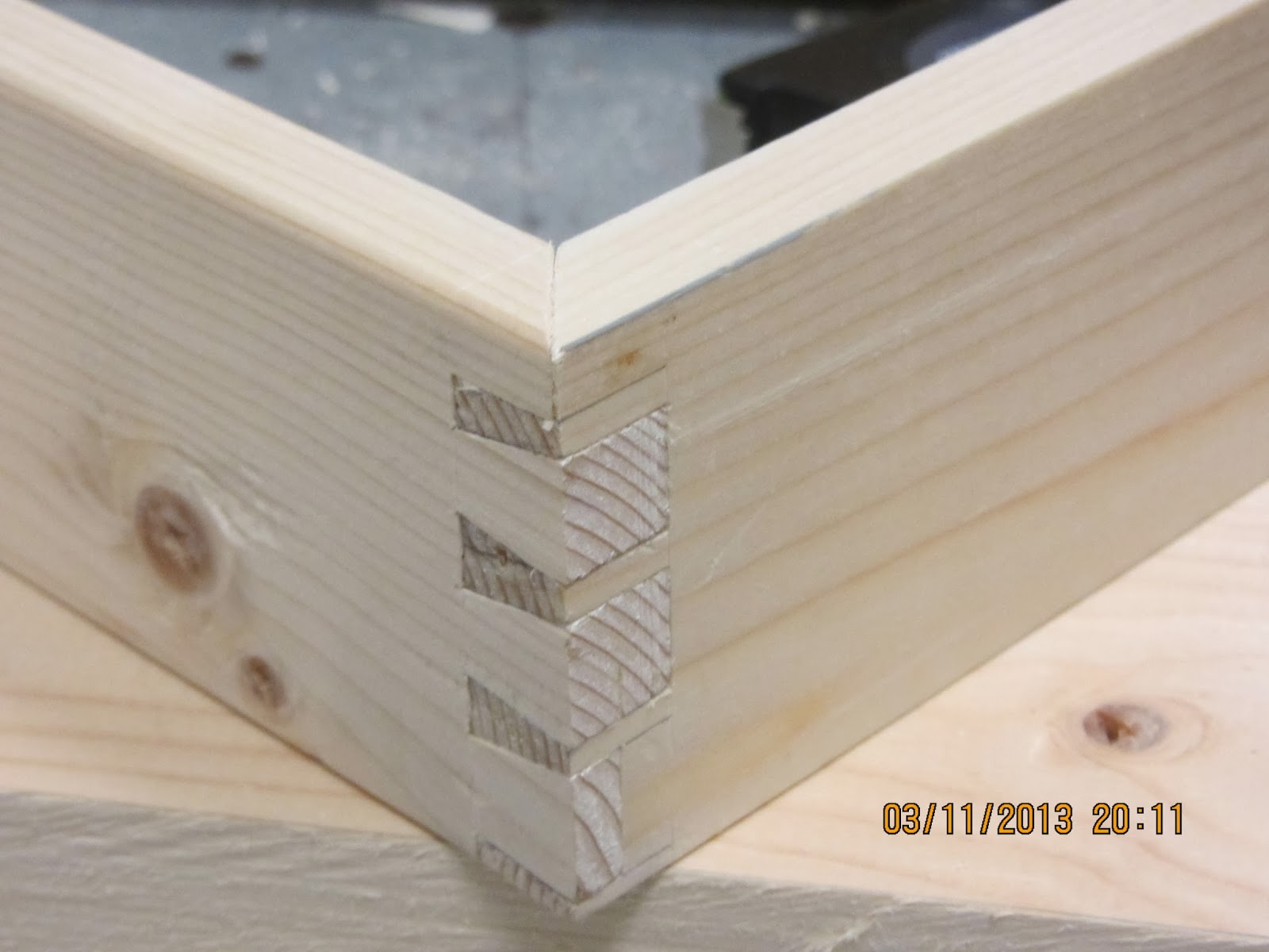
The lid of the chest is built up with a floating panel inside a frame with mitered bridle joints.
I found a wide board for the panel. It came from a set of folding sides for a pallet. It is about 7.5" wide, and it was actually pretty flat and OK in terms of knots. Not exactly furniture grade, but better than the stuff tha I used for the chest itself.
The panel was thinned down to a thickness of 15 mm, and smoothed. Then I planed grooves all around to a depth of approximately 5 mm.

The frame was ripped out of some of the 6x1.5" lumber that I have, so I could save the rest of the pallet side for next time I need a wide board.
The individual pieces were dressed and I decided for their position. I am not good at making boards of an equal thickness, but I decided that I could just make the grooves with the upper side as a reference side, and then once the frame is assembled, I can plane of the bottom, so any inaccuracies will be removed.
If you can make boards that are uniform in thickness, layout is a lot easier, since you can use the same setting for each corner. But you can also work your way around it like I do, and flatten things later.  I don't advocate this approach, you will be much better off, learning to process stock so that it will be uniform.

I generally try to start making joinery from the back of the piece I am working on. This was a trick I was taught by Chris Schwarz at an ATC class in Metten. If you do it that way, you will start making the least visible joint, so any inaccuracies will be on the back of the piece.
My two first mitered bridle joints didn't look particularly good. But they will be on the back side of the lid, so they won't be that prominent.
I discovered that I am not very good at sawing tenons and mortises  with my Japanese dozuki. (I am not sure if that is the correct name when the "mortise" is open in one end?)
Therefore I decided to play the safe card for the front joints and found a hacksaw with a new blade in it. The kerf is somewhat wider, but I find it easier to control such a saw. The result is that the front joints look OK.
I really can't blame the Japanese saw since my model isn't intended for making tenons. It is cross filed, and there is a steel back on it. Using a tool beyond its design is never the best way to go.

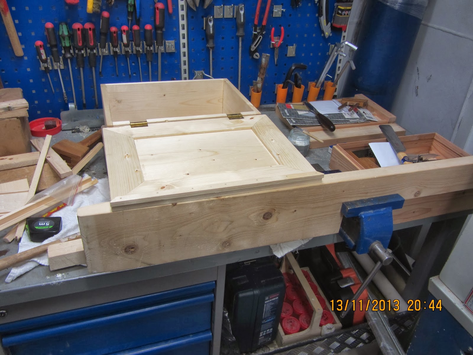
I made a preliminary dry assembly of the lid, but I need to do a little adjusting before the final assembly. Tomorrow I will hopefully glue it together.


the dry assembled lid on top of the chest.

The panel and frame groove connection.


Wednesday, November 6, 2013

Seaborne chest part 6, assembly and hardware

Yesterday I finished the bottom. I sawed off the small repair pieces I had inserted in the knot holes.
I trimmed the dovetails of the upper part with the plane and then I decided that it wouldn't hurt anyone to make a dry assembly, just to see what it would look like. I often skip that part because I am anxious to see a project come together. But for this project I had spent so much time in making the bottom and the skirt, so I didn't want to risk spoiling it.

Strangely, everything fitted together perfectly. I had expected some fiddling to be necessary in order for it to come together, but none was needed. I found myself to be ahead of my mental schedule, so I decided that I might as well glue up the skirt with the insert bottom.

Much to my surprise the glue up went downright smoothly, nice tight joints and all. I suppose it really is a good idea to make a dry assembly at first. Maybe I should consider doing that in the future.

I have speculated whether or not this small chest should have some lifts. I didn't bring any with me, so I would have to make them. One evening I played around with some paper and a scissor, and I came to a solution regarding how to make some lifts.

Today I tried to make those lifts. The whole process was pretty straightforward like I had imagined it. The problem started after the first holders were finished.
I became uncertain if it would look good with lifts at all. One of the holders was cut and filed to a fancy shape, but someway it seems that the chest is too small to have real lifts. 
I could make the lifts smaller, but I think I need to be able to get at least 3 fingers inside the handle. And that is the current width. If they are any smaller they are more or less useless. 
There are 2 more basic holders left which are not shaped yet. So I could also try to make some more plain looking lifts, but that wouldn't make them any smaller.
Due to this sudden dilemma about hardware or not, I didn't continue making the loops for the lifts. The plan for those by the way, was to make them out of some 6 mm copper tube with a welding rod inside to stiffen things up a bit.

What do you think, should a small chest have lifts, or is it reserved to larger ones? 
I made lifts for the Sea chest that I built in March, but that one is slightly bigger and somewhat heavier.
The elaborate holder was taped to the end of the chest now so I could get a picture of it. I think it looks better on the photo than it does in real life.

Anyway, I decided to stop the lift manufacturing for the time being and instead I started on making the lid.


The assembled chest

The fancy lift holder.

The lift manufacturing plant

A  basic holder and the fancy holder.

Monday, November 4, 2013

Seaborne chest part 5, tongues and grooves.

Yesterday I managed to finish the dovetails for the skirt, and they look fine. I was so thrilled that I immediately plunged into making the bottom.
The boards for the bottom were ripped out of a plank, and subsequently dressed to thickness using the scrub plane. This time I did take a picture of my work holding for ripping . It is hard work even though the board is just 4.5" wide. It reminds me a lot of making tenons which I am not very good at.

After a dry assembly of the skirt, I measured the distance to get the correct length for the bottom. The bottom will be made out of 3 boards. The inner one slightly narrower than the two boards. My philosophy is that it will be easier if I just have to rip one board to the final width instead of taking a little of 3. That way if anything went wrong with the tongue and groove planing I didn't have to make new boards.

I adjusted my grooving plane and clamped the boards to the side of a plank which was clamped to the work table. So for this setup I have doubled the number of clamps needed.

After planing the two grooves needed for joining the 3 boards, I started planing the tongues that will go all around the bottom to fit into the grooves in the skirt.

A tongue can be seen as a piece of wood surrounded by two grooves. At least that is how I looked upon the task, because then it wasn't so hard to make them only with a grooving plane.

To make sure that any inaccuracies in the thickness of the boards wouldn't influence on the uniformity of the tongues, I planed from the same side all the time.
Before starting I had decided which side of the boards that was going to be visible from inside the chest. So that side was also going to be the reference side for the fence of the plane.

After making the tongue, there is still a little wood left on the outside of the groove. This I plan on removing with a chisel.
Much to my surprise, the planing of the end grain went smoothly. I made a small bevel with a chisel on the far side of the board to prevent ripping of fibers
I didn't quite finish the boards since one of them had a crack that started to split at the first end grain planing. This crack was glued and I hope to finish the bottom boards altogether tomorrow.

The ripping setup.

The dovetail layout of the skirt. (not planed yet)

Work holding for making tongues on the ends.

A tongue surrounded by two grooves an a little bit of waste.

Friday, November 1, 2013

Seaborne chest part 4, messing up the glue up and the dovetail layout

Yesterday I didn't get to do any woodworking since we had to sail from the oil field to the offshore base with a lot of back load from the rig. Since we were scheduled to arrive in the middle of the night, I had to get some sleep before going to the control room for watch duties. 

This evening I could do woodworking again. I started plowing some grooves in the lower part of the boards for the skirt. These are going to hold the bottom. That part went smooth, greatly aided by my fabulous work holding.

I then decided to glue together the upper part of the chest. I even made a dry assembly first to check the diagonals etc. Everything looked great. I applied the glue and started pressing the boards together. One of the corners needed a little persuasion, so I grabbed a large hammer and placed a narrow board over the tail to be bashed in.. and WHACK. I made an ugly depression that needs to be planed away. Furthermore I actually damaged the wood in the process as well. But at least I achieved my somewhat strange goal of putting the lot together without the use of clamps. I don't really know why I wanted to try this, but it seems as it wasn't the best idea I have ever had. The assembly is square, so I guess that it will be OK in the end anyway. 
When it comes to drying a glued up assembly, few things beat to place the assembly on top of a 690-450 V transformer. That is highly recommended. A nice flat surface and a good temperature.

The whack was still nagging me, so I decided that I needed to do something that could raise the spirit again.
Dovetailing is the magic thing.
The corners of the skirt would be the logical thing to dovetail to at least pretend that the evening had been a success. I had a lot (too much) self confidence so I decided that I didn't have to look at a picture of the Roy Underhill joiners tool chest to remember the basic dovetail layout of the skirt. I mean, how hard could it be. I have made the original chest about a year and a half ago, so it ought to be a walk in the park.
At first I couldn't remember much about it, so I made a lot of confusing lines with my pencil, and then decided that If I just started sawing I would probably remember how it was supposed to look. 
Alas, 3 pins were marked out with the dovetail marker and the upper miter was also marked. I cut the pins first and then I could see that I had managed to make a very visible uneven distance between them..
My thought was that it was for the back corner, so it would be OK, It will probably be somewhat hidden by paint anyway.
When I made the matching set of tails I could see that I had also managed to mess up the part where the groove should stay invisible from the outside. 
Furthermore the lower part ended not with a half pin, but with 1/6 tail!
That was when I decided to call it a day. 
I didn't take any photos of the various flaws I inflicted upon the project, so you will have to use your imagination.

To prevent any further non functioning dovetail layout issues, I have found a sketch up of the original dovetail layout, and I plan to bring this sketch with me for the next woodworking session.