Monday, December 30, 2013

The moving workshop

I was asked for some pictures to back up my explanation of bad weather. So without further fuss, here they come.

The current wind speed is between 18-20 m/s which is equivalent of 40-45 mph

I guess the height of the waves to be about 3-4 metres, but I am not used to making qualified guesses on the wave height, so they could be bigger.

We are going pretty straight into the waves at this point, so there isn't much rolling/listing at the moment. If we had the waves coming from the side it would be a completely different story.

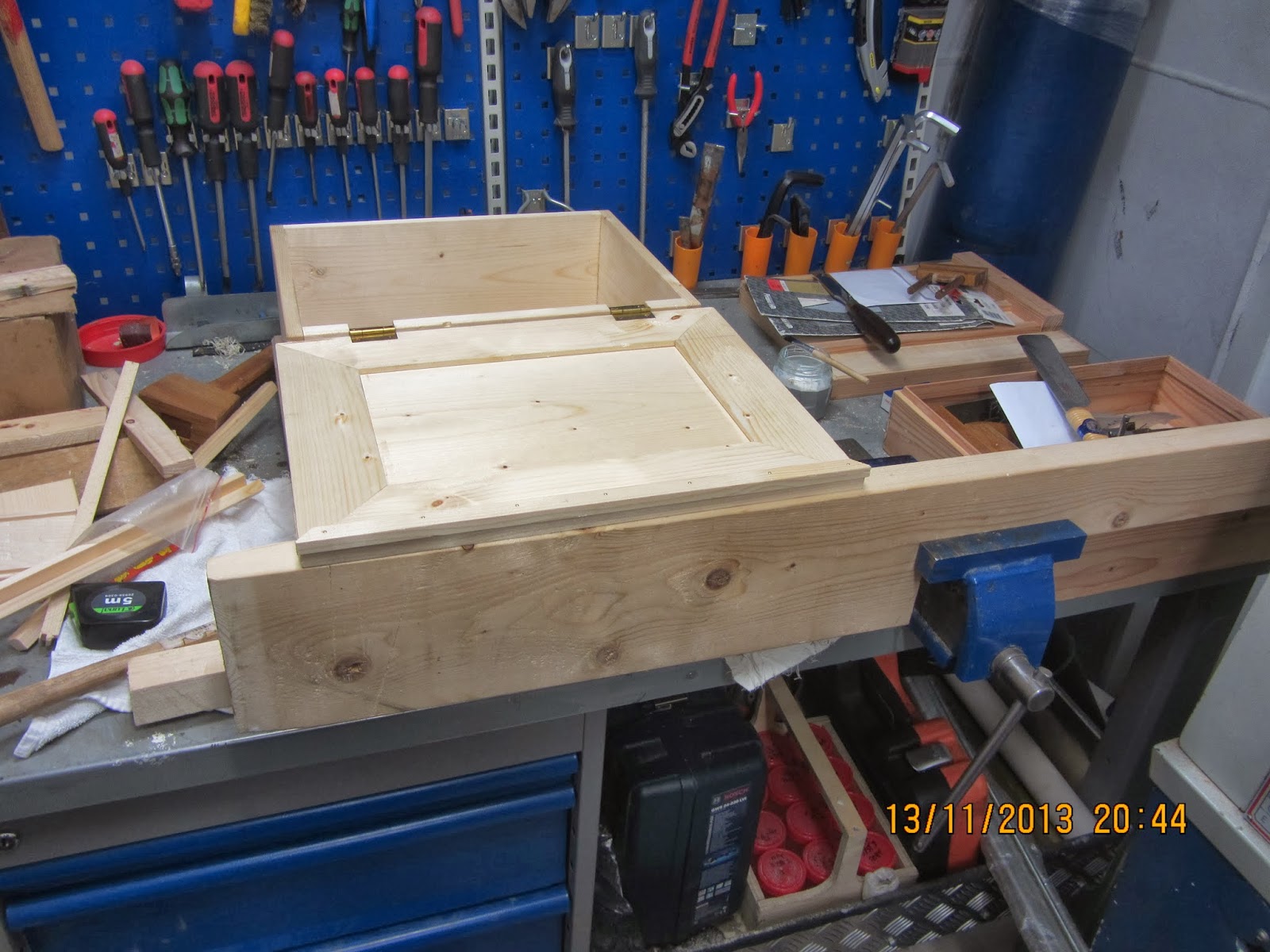
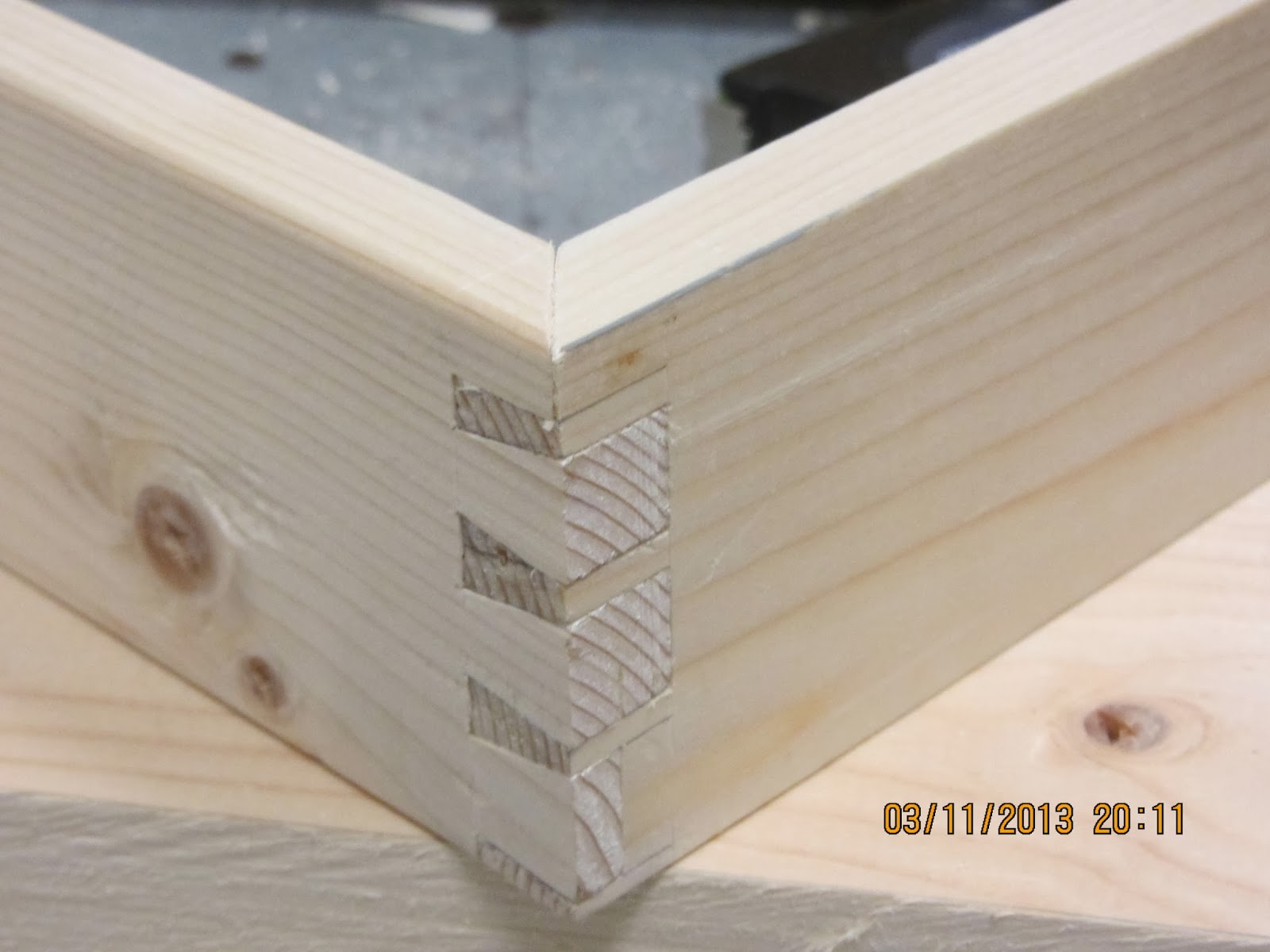
So actually in this weather with the present course woodworking is possible.

Taking pictures of waves isn't easy. You don't really get an idea of the size because there isn't anything that gives a comparable size. Our type of ship has got the accomodation forward, so that is why most of the pictures are facing aft or ove the side.

The ship I am on is a PSV = Platform Supply Vessel.
It is kind of short haul trucking at sea. We supply the platform with e.g. fuel, fresh water, food containers, spare parts and drill mud, drill equipment etc. We also move stuff from the platforms e.g. waste and equipment which is not needed anymore.

The overall length of the ship is 85 m (278') the breadth is 20 m (65'), so it isn't a very large ship. It is very maneuverable though. We have two froward tunnel thrusters and 1 retractable azimuth thruster fwd. At the aft we have two azimuth thrusters (the main propuslsion).

The ship can be seen here: Troms Artemis

Waves and some spray

Some of our deck cargo: Containers and pipes

More waves

View aft, the deck cargo is secured.

The workshop facing aft.

The workshop facing fwd.


Saturday, December 28, 2013

Small hanging cabinet with drawers part 4

We have been severely pestered with bad weather. The North Sea is no joke during the winter months. You can't sleep properly, and a lot of work functions are also limited due to the constant an rather violent movements of the vessel. This includes woodworking during the leisure time..

Today we have been sailing a course where the ship hasn't moved too much, so I decided to do a little woodwork as a Saturday treat.

I started by shooting the ends of the carcase boards. The lid for my little tools chest is also a shooting board. After shooting the first end, I checked with an angle, and found that the shooting board was more off than last time. I rectified the problem by placing a little bit of cardboard behind the carcase board, an easy and quick solution. The boards ended up looking fine and each board in a pair had the same length.

Next I ploughed the grooves for the back panel. This was done using my trusty Stanley grooving plane. The grooves were made before the dovetails in order for me to make a dovetail layout that could conceal the grooves.
I placed the grooves about 5/16" from the edge. This is roughly half the thickness of the back panel. The only problem is that it gives a rather thin half pin for the back of the carcase. I hope it will still be all right.

the dovetails were laid out using my cardboard dovetail marker with a 1:6 angle. The back dove tail is thinner than the other to help conceal the groove.
The weather was still OK, so I decided to start sawing out the pins.
Normally I prefer the tails first approach, but due to the limited work holding out here, I go for the pins first.
I used a hack saw with a almost new blade in it. Actually I doubt that it has been used since last time I was out here, and used it as a tenon saw.
I find it very easy to use a hack saw for dovetail saw. It has a nice weight to it, so it will work its way down the wood just fine. The teeth are fine I can't remember if it is 18 or 24 PPI. If the blade is dull, it takes only a short time to replace it, and the saw is sharpened for rip cuts.
The only backside is that the kerf is a little wider than it would be on a normal fine dovetail saw, but I don't mind.

I chopped out the waste between the pins and left it at that. The weather has turned worse, and there is no point in risking to mess up the carcase by attempting to make the tails during a lot of waves.

The first pins are sawed.

Wednesday, December 25, 2013

Small hanging cabinet with drawers part 3

Merry Christmas.

We were led to believe, that the ship would be alongside for the best part of Christmas. But due to bad weather with heavy winds, things have been delayed, therefore we are going to go back to sea tonight, to deliver some more stuff to a rig. This isn't exactly like winning the sweepstakes, but on the other hand, it is what we are getting paid to do. At least we had Christmas eve alongside.

I used the opportunity of still being alongside, to plane all the re sawn boards that I had made for the project. Planing is also one of those things that are easier, when the workshop is not moving.

The boards from the single use pallet were of a mixed quality. Some of them cupped really bad. All in all, there were three small boards that I decided would be a waste of time to try to plane. If I need some more, I'll have to re saw some later on. But for now I'll see how far my stock can get me. They ended up being a bit thinner than I anticipated, so I am curious as to if I am able to make a groove in them for the drawer bottom.

Yesterday, I glued up the back panel, I decided to leave it in the rough until I am going to use it. There is not much idea to flatten it, if it starts to cup and bow and twist before I get a chance to mount it.
There is a little cupping of the panel as it is right now, but it is actually looking better than I had feared.

Most of the planing today was done with the smoothing iron in the plane. I had managed to re saw the thinner boards so they didn't need that much work. The boards for the carcase were dressed with the scrub iron first, to reduce the thickness a bit. I am amazed at how well my plane iron holds up. Another thing is, that I am getting really good at adjusting the plane - in no time I can have it ready for smoothing, and take a nice full width super thin shaving. I guess that practise really does make perfect.

After finishing the planing, I cross cut the boards for the carcase. Then I cleared up in the workshop. Depending on the weather tomorrow, I might try to shoot the ends of the boards and plane a groove for the back panel.


The planed boards and some shavings.


Saturday, December 21, 2013

Small hanging cabinet with drawers part 2

To me the beginning of a project out here at the sea is the least fun part. Like any other woodworker I need some material to work from. This is commonly known as stock preparation.

At home I would cross cut some wood, and joint it on the jointer, bring it to thickness in the planer, and then get on with the fun part of joining the pieces together.

Out here I have to cross cut the pieces, rip everything with a handsaw, plane the stock to the desired thickness, and then I can get to the joinery.

In an attempt to be a  little more effective than usual, I decided that I would rip most of the wood for the carcase, before starting to plane it.
My last build out here (the seaborne chest) was not made quite that way: I would rip a couple of boards, plane them, find out I needed more, rip again, plane again and so forth..

Yesterday evening and tonight I have been busy ripping a total of 9' (270 cm) of 6" stock. I timed my efforts out of interest, and I can rip 2' in about half an hour with the saw I have available. The surface isn't quite as nice as a band sawn surface would be, but once it will be planed it will be OK.

I have made the initial stock preparations for the sides of the carcase, the back of the carcase and the horizontal and vertical dividers.

The sides are hopefully going to end up being around 1/2" (12 mm) and the back and the dividers around 5/16" (8 mm).
Tomorrow I intend to find an old pallet and see if I can salvage some wood that will be fitting for the drawers. I also need to find the future rails and stiles for the door, but I could always rip those out of the 6" stock if I have to.
If the pallets are too wet, I might decide to rip everything out of the 6" stock, since that is perfectly dry already. The problem is it will require more work from my side.

Ripping a 16 "x 6" into three thin boards.


Friday, December 20, 2013

Small hanging cabinet with drawers part 1

Before going back to sea, I had given some thoughts as to what I would like to try to build this time. I decided that I have made enough chests for a while. On the other hand, it has been a while since I made a cabinet with a lot of small drawers. 

I bought some more small brass hinges to bring with me, and I even decided to bring a lock. I purchased that one years ago without no definite goal, simply because it was on sale.

The sea chest builds were both made without any drawings or sketches. But I figured that it wouldn't hurt to have a rough idea of the problems I might encounter during this build so I made a small sketch.

The principal dimensions are 30 x 40 x 14 cm (12" x 16" x 5.5"). This should give a nice small cabinet that can be transported home as luggage without any problems. With a depth of only 14 cm I won't have to glue up any side panels, but I can get them out of the lumber that I have on hand.
This time we are even so lucky as to have some old single use pallets lying about, so maybe I won't have to rip as much as I did when I made the seaborne chest.

The door is what is troubling me the most. 
If I make a planted door, I can gain access to the drawers that are in the hinge side of the cabinet. But then I can't make the lock work, because it needs to enter a mortise. This could be overcome by adding a small portion on the inside of the door, so the lock would be further in than the actual door. But that would mean that I would have to make some of the drawers shorter than the rest, and I am afraid that it would look strange.

If I make an inset door, with then hinges set into the door, the left side drawers can't come out. That could be overcome by adding a small board inside, thus starting the drawers about 1/2" from the actual side of the carcase. I think this will look the best.
It is also possible to make an inset door with the hinges set into the frame. That way I won't have to add any boards to the inside of the carcase, but the look will be slightly different.
An inset door will allow the lock to be fitted as it should.

Then there are the various design possibilities of the door itself: 
It could be made with mitred bridle joints at the corners, I think that would look good if I made mitred dovetails at the front corners as well.

On the other hand,  it could be made with regular mortises and tenons giving rails and stiles at right angles to each other. That would probably look best together with a normal dovetailed corner.

The idea is that the cabinet should be able to be mounted on a wall, so I plan on making the pins on the top and bottom of the carcase. I'll just go for regular through dovetails for the carcase.
There will be plenty of half blind dovetails at the drawer fronts.

The calculations on the sketch is for the height of the graduated drawers. 


My building sketch with design possibilities


Monday, December 16, 2013

Large knobs made on the lathe

After installing the oversized peg board, and moving the stable sheets (rugs), I installed an old shelf in the saddle room. This helped organize all the odds and ends that always seem to acumulate in a short time. SWMBO asked if I could make something that would hold the riding helmets, thus freeing space that could be used for the bridles instead. 

I quickly acccepted and this morning I turned some nice pegs. They look like mushrooms on steroids. 
The turning was made with two mushrooms made out of 1 blank. They were then separated using a saw and then ends trimmed using a chisel.
The mounting was done by boring a pilot hole in the base of the mushroom and then screwing from the back of the panel where they were fitted.

Those were then installed on the side of the shelf, and then entire project took about 2 hours including turning and mounting. This is way faster than my ususal projects, but then again it wasn't complicated in any way. 

I was able to fit 4 "mushrooms" for helmets, and the remaining 4 were installed near the box of each horse for holding the halters.

4 pairs of mushrooms.

8 mushrooms ready for being mounted

The mushrooms mounted on the side of the shelf.
1 helmet removed for explanation purposes.

Friday, December 13, 2013

Peg board for the stable - installed

With the future hide glue out in the fresh air, I drilled the holes in the wall using the hammer drill function. I am convinced that the noise would have caused the horses to frown, so it was better to have them out of the way before doing the noisy part of the job.
I went into town and bought some 6" screws, and then I mounted the peg board. The left side of the left board sunk a little during mounting, since the drill just hit below a brick and the wandered of to the easier soft mortar. But I doubt anyone will notice.

Laura helped to hang up the stable sheets, and it looks as it is working just according to the intended plan.
The stable sheets just clear the ground which is perfect.

I tried to take some pictures showing the moulding, but photography is not my strongest side.

Stable sheets hung on the pegs.

End detail showing the moulding profile.

Complete with Roman numerals.


Thursday, December 12, 2013

Peg boards, table and benches

Today I finished the peg boards for the stable. Since the project had gone smoothly so far, I decided that it would be a fine idea to test a moulding plane.
I have never worked with moulding planes before, but I have a few old ones lying about.

The choice fell on a pretty simple beading profile. During the entire process I became painfully aware that I had not paid any attention whatsoever as the the grain direction of the boards with respect to the moulding plane. The moulding plane is not symmetrical, so I couldn't stand the board on an edge and plane with the grain.. The result left quite somewhat to be desired in terms of finish. I reground the blade a couple of times to get an even shaving, and in the end the plane behaved OK. Maybe one day I'll try it out on a piece of wood with the correct grain orientation.
For my comfort I kept on reminding myself that it is for the stable, and it can look a little rustic. I also sanded the beading lightly after finishing, so the result is OK. Actually it is more than OK. I am impressed at the impact a simple moulding had got on a board. Previously I would have just chamfered the edges - and that would only be in case I wanted to make the piece extra nice. But the beading makes it look a lot more finished and refined.
Sadly I was unable to hang the boards up on the wall, since I didn't have any 6" screws left. I'll have to go to town tomorrow and buy some. The reason for the very long screw is that the inner wall of the stable is covered with 3" of insulating bricks that are very soft. So in order for the boards to be secured decently, I have to drill through all that and into the real bricks.

A friend of mine is active in the World of model aircraft. The local club which he is a member of has just rebuilt their club house. They asked me if I could make some rustic looking tables and benches? I have been thinking about a design for those for a long time.
I prefer tables like that to be collapsible. That makes them easier to move and to store in case they need the meeting room for something else.
Benches on the other hand should be as sturdy as possible without being clumsy.
Since the club has offered me to pay for the stuff, I had to figure out what the cost was going to be. So as an experiment I decided to try to work as effectively as I could, and not be overly attentive to hidden details that wouldn't matter regarding strength or function.
I was very surprised to find out that I could knock together a good looking sturdy table in 6 hours and 20 minutes. Off course it helps greatly that The only finish is a quick run over with a random orbit sander and grit 80.
The most difficult thing is that when you can't square up stock due to requests from the "customer", you have to work without a lot of the normal possibilities of measuring that you usually have.

For the benches I turned to the Shaker bench that I have made before. Only this time it too had to be made out of unprocessed stock.
The bench took a lot longer to build than I anticipated. I guess it is due to the fact that there are a lot more joints to be made, and all of them has to be made  more or less by hand. Working as fast as I could, the bench took me a little more than 4 hours. I can't remember the exact time, and I am too lazy to go to the workshop to check it out.


A crappy picture of the two peg boards

The table and the first bench

A sliding dovetail is holding the table top.
The legs are inserted into mortises in the stretcher

Wednesday, December 11, 2013

Peg board for the stable

As many woodworkers know (and even more have heard of), hide glue is working best when it is warm.
The funny thing is that this adage is also true when it comes to hide glue in the rough.
In order for the future hide glue to keep warm during the cold months they are fitted with stable sheets. These take up an impressive amount of space in the saddle room, and when they are wet they take forever to dry if they are not hung upon something. In an attempt to keep SWMBO happy, I have offered to make an oversized peg board for this task.
Part of my reason for offering to make this project is that I rediscovered how much fun it can be to turn stuff on the lathe. So I wanted to turn some more.

The pegs are mostly made out of white thorn that I have salvaged from our own hedge once I cut it back quite drastically. A few of the pegs are made out of apple. White thorn is almost as easy to turn as apple, and I had a lot pieces lying around of an appropriate thickness.

The length of the pegs from end to the start of the tenon is approximately 6". The tenon is 1" except for the first peg I made, which I made it 11/8". I switched to 1" after testing the two drills and found that my 1" drill was superior.

The pegs waiting for me to find a board for them.

Monday, December 9, 2013

Seaborne chest part 10 (the end)

I finally pulled myself together and finished the sea chest.
After a lot of various obstacles such as a course north of the Polar circle, a heavy storm and 80 cubic meter of sea shells - today seemed like the right day to end the project.

The traditional way of attaching the beckets to the cleats is by means of an axle made out of rope. In order to make a nice diamond knot, you need at least some 4 stranded rope (or a higher number).
I don't have any rope of that kind lying about, and I don't want to purchase some just for making two small axles. So instead I decided to turn some axles instead.

I made the axles out of some old apple tree that I had once saved for turning purposes. Turning old fruit tree like apple, pear or plum etc. is a joy. The turning itself went conspicuously smooth, and that is rather strange since I don't do much turning. I turned two axles with a dome shaped end, and two loose domes that were drilled out afterwards - and then glued on to the axles (with the beckets installed)

I made the recesses of the cleats little deeper, to accommodate the domes, and then I simply screwed them onto the ends of the chest. I didn't use any glue in case someone will want to disassemble the arrangement in the future to renew the beckets when they are worn out.

For a finish I have thought about painting the chest, but I ended up deciding for a pure oil finish. I read on the can of Kamelia oil I have, that it can be used as a finish. Since the whole chest has been sort of an experiment, a new type of finish seemed just right. The oil penetrated the wood impressively easy, and I have now left the first coat to dry. I guess that I will add three coats in total.

What did I learn about this build:
The correct tools really do a difference. A scrub plane was probably the biggest difference from my previous sea chest build.
The nice looking Crown of Sheffield chisels that I had brought with me are nice looking and comfortable to use, but they can't hold the edge. They are so soft that I had to resharpen them way too often considering that the wood is soft pine. So I don't recommend anyone to buy that model of chisels. It is actually a shame since the tapers of the sides are nice and thin, and the name Sheffield used to be synonymous with high quality steel years ago.
Peer pressure got me into making beckets and cleats. Looking at the finished chest, I have decided that I think they look a little too extravagant. I have to admit that I am more into Shaker simplicity than fancy rope work. But I guess that I would never have found out if I hadn't tried.

All in all a nice little project that is possible to make even without a proper workbench.

Sea chest with beckets

Small sea chest with beckets

A blown out hole in the barn made by the heavy weather.

Thursday, November 21, 2013

Beckets for the seaborne chest

Since I had given myself the challenge to make some beckets for the chest, I decided that I'd might as well do it properly.

Yesterday while I was still on the ship, I managed to finish the coachwhipping of the two beckets.
One of the few advantages of a long maneuver watch is that you get to sit quietly in the control room and can do stuff like those beckets. Provided off course, that nothing requires you to act on a machinery situation e.g. an alarm.

I made it home late yesterday evening, and after completing some of the major items on my wife's dock list (the list of things I have to mend when I am home) I decided to add some finishing touches to the beckets.

One of the classic ways to end a becket is by a Turks head knot. I decided to go for a 5 stranded Turks head knot. I have a book that shows basically how it is made, and after a test, I finished the 4 ends of the beckets.

Now I have to find some material for the axles, and then I am a bit closer to finishing the chest altogether.

The eye with ringbolt hitching and 5 stranded Turks head.

The finished pair of beckets, awaiting the axles. 

Friday, November 15, 2013

Seaborne chest part 9, cleats and beckets.

With the basic chest completed, I have started making the handles for it.
As per popular demand from the readers of this blog, I am trying to go the traditional route and installing cleats and beckets.
I won't be able to finish those while on board, since we don't have any leather. The leather is required for the axle.

I am making my beckets approximately half the size since the chest is also smaller than a normal sea chest, roughly half the size. So my guess is that it will end up looking OK.

Becket making wasn't being taught at the basic seaman school I attended (Kogtved Søfartsskole). 

So I trawled the Internet and found this page which is an absolute treasure trove concerning rope art. 
There is a tutorial on making beckets + loads of other stuff. 

It is recommended that the beckets are like, so I made a small device for starting my beckets. That way I can start both of them at the same time, and they will be equal in length. The core material is tarred marline, and it smells a lot! 
The lighter brown material is hemp twine. 
I hope the smell of the tar will disappear over time, if not I'll have to keep the chest in the barn.

As can be seen on the lower picture, I have made a test becket to try some of the techinques required. You can also see the two cleats that will be attached to the chest once I get home and have access to some longer brass screws again.


Making two beckets at the same time

My test becket and the two cleats.

Wednesday, November 13, 2013

Seaborne chest part 8, the improved dust seal

I glued up the lid itself yesterday, and just to make certain things weren't going to get too easy they called from the bridge right in the middle of the glue up.. I had to hurry to a telephone and then race into another section of the ship (the upper cement room), open a bypass valve, then back to the telephone to tell it was ready and finally back to the glue up.
After the glue up, I processed some wood to make small strips for the dust seal.

Today we are still so lucky as to be alongside which makes it a lot easier to do woodworking compared to when the ship is rolling.

I leveled the underside of the lid, and then I installed the brass hinges that I had brought with me. The heads of the brass screws are a little on the large side, but those were the ones I chose to bring. I was actually a little smart, since I brought both 1/2" and 3/4" screws. The smaller ones were just the right size for attaching the hinges to the lid.

My original plan was to make a traditional dust seal i.e. the front and the two sides. I didn't bring any small brass screws that would be fitting for attaching the dust seal, but I did bring some small brass nails that had the right size.
The strips of wood were mitered in the corners and pilot holes were drilled. I then put nails in all the pilot holes and hammered them almost through, so that a small tap from a hammer would make them enter the lid.

I closed the lid and brought the strip into position so it touched the front side of the chest. I then gently hammered 3 nails in to keep the position. After that I opened the lid and placed it on a supporting plank that was held in the vice. That took the stress of the hinges while I hammered the final nails in.
The same procedure was used for the strips on the side.

All strips were made too wide on purpose.  That allowed me to plane them flush with the edge of the lid after the glue had dried. The advantage of this idea is that it doesn't matter if the lid is just a little out of square. You will still get a tight seal and a flush surface.

The dust seal works works just as it should, but I got the idea that I could make an improvement on this type of dust seal. (To make as perfectly as possible).

Dust can enter everywhere there is a small hole or opening, and the back of the lid with the hinges normally don't get a dust seal since it will prevent the lid from opening. That is if you put the dust seal on the outside.
If you put a dust seal on the inside of the lid, you can seal the back as well.
After making some more strips for my improved dust seal, I measured and mounted it. To avoid any unfortunate screw ups, such as a wrong placed dust seal strip causing the lid to not close, I tacked the strips on with only two nails for a start. Then after checking that the lid would still close, I removed the strip and glued and nailed it in place.

A good thing about this extra dust seal is that it can be mounted on an existing chest If anyone should wish to do so. You just have to make sure that it won't collide with e.g. a sliding till in the chest.


The dust seal planed flush.

The supporting system for nailing on an attached lid.

The improved dust seal.


Monday, November 11, 2013

Seaborne chest part 7, the lid

After a couple of very hectic days with a semi blown up clutch between a motor and a generator, a complete test of all our redundancy systems and a stay alongside a repair quay in order to have our exhaust pipes extended things have finally settled down to a normal pace.

Thus tonight I was able to relax and recharge my personal batteries by going to the workshop and continuing with the lid.

The lid of the chest is built up with a floating panel inside a frame with mitered bridle joints.
I found a wide board for the panel. It came from a set of folding sides for a pallet. It is about 7.5" wide, and it was actually pretty flat and OK in terms of knots. Not exactly furniture grade, but better than the stuff tha I used for the chest itself.
The panel was thinned down to a thickness of 15 mm, and smoothed. Then I planed grooves all around to a depth of approximately 5 mm.

The frame was ripped out of some of the 6x1.5" lumber that I have, so I could save the rest of the pallet side for next time I need a wide board.
The individual pieces were dressed and I decided for their position. I am not good at making boards of an equal thickness, but I decided that I could just make the grooves with the upper side as a reference side, and then once the frame is assembled, I can plane of the bottom, so any inaccuracies will be removed.
If you can make boards that are uniform in thickness, layout is a lot easier, since you can use the same setting for each corner. But you can also work your way around it like I do, and flatten things later.  I don't advocate this approach, you will be much better off, learning to process stock so that it will be uniform.

I generally try to start making joinery from the back of the piece I am working on. This was a trick I was taught by Chris Schwarz at an ATC class in Metten. If you do it that way, you will start making the least visible joint, so any inaccuracies will be on the back of the piece.
My two first mitered bridle joints didn't look particularly good. But they will be on the back side of the lid, so they won't be that prominent.
I discovered that I am not very good at sawing tenons and mortises  with my Japanese dozuki. (I am not sure if that is the correct name when the "mortise" is open in one end?)
Therefore I decided to play the safe card for the front joints and found a hacksaw with a new blade in it. The kerf is somewhat wider, but I find it easier to control such a saw. The result is that the front joints look OK.
I really can't blame the Japanese saw since my model isn't intended for making tenons. It is cross filed, and there is a steel back on it. Using a tool beyond its design is never the best way to go.

I made a preliminary dry assembly of the lid, but I need to do a little adjusting before the final assembly. Tomorrow I will hopefully glue it together.


the dry assembled lid on top of the chest.

The panel and frame groove connection.


Wednesday, November 6, 2013

Seaborne chest part 6, assembly and hardware

Yesterday I finished the bottom. I sawed off the small repair pieces I had inserted in the knot holes.
I trimmed the dovetails of the upper part with the plane and then I decided that it wouldn't hurt anyone to make a dry assembly, just to see what it would look like. I often skip that part because I am anxious to see a project come together. But for this project I had spent so much time in making the bottom and the skirt, so I didn't want to risk spoiling it.

Strangely, everything fitted together perfectly. I had expected some fiddling to be necessary in order for it to come together, but none was needed. I found myself to be ahead of my mental schedule, so I decided that I might as well glue up the skirt with the insert bottom.

Much to my surprise the glue up went downright smoothly, nice tight joints and all. I suppose it really is a good idea to make a dry assembly at first. Maybe I should consider doing that in the future.

I have speculated whether or not this small chest should have some lifts. I didn't bring any with me, so I would have to make them. One evening I played around with some paper and a scissor, and I came to a solution regarding how to make some lifts.

Today I tried to make those lifts. The whole process was pretty straightforward like I had imagined it. The problem started after the first holders were finished.
I became uncertain if it would look good with lifts at all. One of the holders was cut and filed to a fancy shape, but someway it seems that the chest is too small to have real lifts. 
I could make the lifts smaller, but I think I need to be able to get at least 3 fingers inside the handle. And that is the current width. If they are any smaller they are more or less useless. 
There are 2 more basic holders left which are not shaped yet. So I could also try to make some more plain looking lifts, but that wouldn't make them any smaller.
Due to this sudden dilemma about hardware or not, I didn't continue making the loops for the lifts. The plan for those by the way, was to make them out of some 6 mm copper tube with a welding rod inside to stiffen things up a bit.

What do you think, should a small chest have lifts, or is it reserved to larger ones? 
I made lifts for the Sea chest that I built in March, but that one is slightly bigger and somewhat heavier.
The elaborate holder was taped to the end of the chest now so I could get a picture of it. I think it looks better on the photo than it does in real life.

Anyway, I decided to stop the lift manufacturing for the time being and instead I started on making the lid.


The assembled chest

The fancy lift holder.

The lift manufacturing plant

A  basic holder and the fancy holder.

Monday, November 4, 2013

Seaborne chest part 5, tongues and grooves.

Yesterday I managed to finish the dovetails for the skirt, and they look fine. I was so thrilled that I immediately plunged into making the bottom.
The boards for the bottom were ripped out of a plank, and subsequently dressed to thickness using the scrub plane. This time I did take a picture of my work holding for ripping . It is hard work even though the board is just 4.5" wide. It reminds me a lot of making tenons which I am not very good at.

After a dry assembly of the skirt, I measured the distance to get the correct length for the bottom. The bottom will be made out of 3 boards. The inner one slightly narrower than the two boards. My philosophy is that it will be easier if I just have to rip one board to the final width instead of taking a little of 3. That way if anything went wrong with the tongue and groove planing I didn't have to make new boards.

I adjusted my grooving plane and clamped the boards to the side of a plank which was clamped to the work table. So for this setup I have doubled the number of clamps needed.

After planing the two grooves needed for joining the 3 boards, I started planing the tongues that will go all around the bottom to fit into the grooves in the skirt.

A tongue can be seen as a piece of wood surrounded by two grooves. At least that is how I looked upon the task, because then it wasn't so hard to make them only with a grooving plane.

To make sure that any inaccuracies in the thickness of the boards wouldn't influence on the uniformity of the tongues, I planed from the same side all the time.
Before starting I had decided which side of the boards that was going to be visible from inside the chest. So that side was also going to be the reference side for the fence of the plane.

After making the tongue, there is still a little wood left on the outside of the groove. This I plan on removing with a chisel.
Much to my surprise, the planing of the end grain went smoothly. I made a small bevel with a chisel on the far side of the board to prevent ripping of fibers
I didn't quite finish the boards since one of them had a crack that started to split at the first end grain planing. This crack was glued and I hope to finish the bottom boards altogether tomorrow.

The ripping setup.

The dovetail layout of the skirt. (not planed yet)

Work holding for making tongues on the ends.

A tongue surrounded by two grooves an a little bit of waste.

Friday, November 1, 2013

Seaborne chest part 4, messing up the glue up and the dovetail layout

Yesterday I didn't get to do any woodworking since we had to sail from the oil field to the offshore base with a lot of back load from the rig. Since we were scheduled to arrive in the middle of the night, I had to get some sleep before going to the control room for watch duties. 

This evening I could do woodworking again. I started plowing some grooves in the lower part of the boards for the skirt. These are going to hold the bottom. That part went smooth, greatly aided by my fabulous work holding.

I then decided to glue together the upper part of the chest. I even made a dry assembly first to check the diagonals etc. Everything looked great. I applied the glue and started pressing the boards together. One of the corners needed a little persuasion, so I grabbed a large hammer and placed a narrow board over the tail to be bashed in.. and WHACK. I made an ugly depression that needs to be planed away. Furthermore I actually damaged the wood in the process as well. But at least I achieved my somewhat strange goal of putting the lot together without the use of clamps. I don't really know why I wanted to try this, but it seems as it wasn't the best idea I have ever had. The assembly is square, so I guess that it will be OK in the end anyway. 
When it comes to drying a glued up assembly, few things beat to place the assembly on top of a 690-450 V transformer. That is highly recommended. A nice flat surface and a good temperature.

The whack was still nagging me, so I decided that I needed to do something that could raise the spirit again.
Dovetailing is the magic thing.
The corners of the skirt would be the logical thing to dovetail to at least pretend that the evening had been a success. I had a lot (too much) self confidence so I decided that I didn't have to look at a picture of the Roy Underhill joiners tool chest to remember the basic dovetail layout of the skirt. I mean, how hard could it be. I have made the original chest about a year and a half ago, so it ought to be a walk in the park.
At first I couldn't remember much about it, so I made a lot of confusing lines with my pencil, and then decided that If I just started sawing I would probably remember how it was supposed to look. 
Alas, 3 pins were marked out with the dovetail marker and the upper miter was also marked. I cut the pins first and then I could see that I had managed to make a very visible uneven distance between them..
My thought was that it was for the back corner, so it would be OK, It will probably be somewhat hidden by paint anyway.
When I made the matching set of tails I could see that I had also managed to mess up the part where the groove should stay invisible from the outside. 
Furthermore the lower part ended not with a half pin, but with 1/6 tail!
That was when I decided to call it a day. 
I didn't take any photos of the various flaws I inflicted upon the project, so you will have to use your imagination.

To prevent any further non functioning dovetail layout issues, I have found a sketch up of the original dovetail layout, and I plan to bring this sketch with me for the next woodworking session. 


Wednesday, October 30, 2013

Seaborne chest part 3, work holding

Today I finished the remaining 3 corners of the upper part of the chest. I noticed that my last dovetails were better than the first set from yesterday, but that is usual. After all I don't make dovetails every day, so the first set is kind of like a brush up practice.

I have developed some work holding methods that are working well on a ship. They would also work well in a garage with a work table and a mechanics vice. Basically I get by using the vice and 3 pieces of wood and 1 clamp.

I try to never clamp the wood for the project directly in the mechanics vice, as the jaws easily mar the surface.

For dovetailing lay out and sawing. A piece of wood is held in the mechanics vice, and the piece to be dovetailed is held on to the fixed piece by means of a clamp and an extra small piece of wood to protect the surface from the clamp.

For chopping out the waste between the pins or tails. The piece to be worked on is positioned on top of a wide board. A small piece of wood is placed a bit away from the end, and a longer piece of wood is placed on top of the small piece and on top of the piece to be held. A clamp is used to press the longer piece of wood down. The same principle as in a leg vice, just horizontal.

When I need a planing stop, I use the wide board as a base, and position the small piece with one end on the wide board, and the other end on the work table. Then I just clamp it down and it holds the wide board and acts as a planing stop at the same time.

When I plane the grooves, I turned the long piece of wood so it was with the broad side up in the vice, and clamped the pieces to be planed on top. Again I used the small piece and a clamp.

I will be the first to admit that working on a proper workbench is easier. But lack of a good workbench shouldn't necessarily keep anyone from doing a little bit of woodwork.


Dovetailing setup


Chopping setup

My dovetail marker.


Tuesday, October 29, 2013

Seaborne chest part 2

Yesterday I smoothed the boards using the smoothing iron for the plane. It was easy and satisfying. When I was done, I crosscut the pieces to length and then I used my lid based shooting board to clean up the ends. I am not used to working with a shooting board, so the first end I managed to tilt the plane and messing up the end a little. Once I noticed it, I corrected the fault.So basically it was a success with the shooting board.
I guess that a metal plane might be a little easier for this job since there is not much weight in a wooden smoother. But you can't have light weight for travelling and heavy weight for shooting.

After the shooting, I sharpened the blade of the grooving plane. I only have one blade for it which is 5/32. For the thickness of my stock, a groove of 1/4" would probably have been a little more appropriate, but Instead of making two parallel grooves adding up to the desired width, I decided that 5/32" isn't going to hurt anybody. I could probably make a new blade for the plane some time, but I don't feel for it right now.

I ran some tests on the grooving plane as well, and adjusted it to the grooves I have decided on for attaching the skirt of the chest.

Today I planed / plowed the grooves on the boards. I have made the grooves a tiny bit further in on the board than the actual width of the groove. That way, I can always adjust the fit by planing a little of both pieces. I tested the interlocking grooves, and they were a bit tight, so maybe I will need to resort to planing them once I am attaching the skirt.

When I cut dovetails, I normally like the tails first approach, but on a ship without decent work holding, it is easier to do it pins first. The pieces are so small, that that it is not difficult to balance them on an end for marking the tails. So that is how I do it out here.
I made one set of dovetails, and they were OK.

I haven't found a miter gauge, so instead I used a small stiff piece of cardboard as a dovetail marker. I cut of one side in a ratio 1:6 which is pretty standard for soft wood.

Tomorrow I plan on continuing with the dovetails.


The shooting board lid of the tool chest.


Sunday, October 27, 2013

Seaborne chest part 1

The tool chest for the sea made it on board in one piece, and today I had the opportunity to start a new project.

On the Siem Marlin I was spoiled by having plenty of exotic pallet wood. I even have a perfect 12” wide board of idigbo waiting for me if I ever get back to that ship, provided off course, that no one have used it in the meantime. The wood we have here is by no means furniture grade stuff. All I have managed to find is 1.5” x 6” pine used for construction purposes. I had hoped for some pallets or pallet sides, but we don’t have any. So as usual I’ll try to get by using what is available.

I decided to build a small chest based on the Roy Underhill joiner tool chest, because I have always liked that chest. Furthermore I think it will look OK even with a coat of paint on it. That might be necessary since I am afraid there will be some missing knots etc. which will be hard to conceal.
The major dimensions of the chest will be roughly 8” x 12” x 16”.  I don’t want to build anything that will be too large due to the challenge of getting it home once it is finished.

Stock preparation began by crosscutting the lumber to length. We have got a cheap standard 22” saw with combination toothing on board. I used it for ripping the pieces to half the thickness, which was quite a big job. The pieces actually looked better than I had hoped for straight from the sawing.

I managed to rig up some work holding using a piece of the construction lumber as base and a small piece of wood as a planning stop. The planning stop was clamped to the workbench and it worked great. The best thing though was that I was able to use my scrub plane for dressing the stock. It was so easy I could hardly believe it. 
Nice curly shavings.

Friday, October 25, 2013

Building model houses with the children.

In the autumn holiday we spent a couple of days in our summerhouse. There is no TV signal there, and normally we try to make some things that we wouldn't take the time to do at home. e.g make models using my old Mecano / Constructor set.
This year I had decided to try a new project: Model houses.

Before driving to the summerhouse, I made a large amount of model timber and model planks for the project.
Timber: 1/2" x 1/2"
Planks: 1"x 1/8"
Planks: 1/2" x 1/8"
All approximately 2 feet long.

For bases I had brought some pieces of plywood and a piece of a table top. Furthermore I brought some triangular pieces made from a 1" thick stock, about 2" wide. These became the steps of a staircase.

The only tools used for the build was a hot glue gun and a moulding / miter scissor.

Asger decided to build a barn and Gustav decided to build a house. I showed them a few ideas regarding how the things could go together so it would look like a real scale model of a building.
The scissors do require a little hand strength, so I got the laborious task of being the lumber yard. They would then say what type of timber or plank they would need, and the size of it, and I would provide it from the stock that we brought.

The structure went together fast using the hot glue gun, and the build could continue without having to wait for glue to dry. When a thing didn't look right to them, it was still possible to cut of the piece again using a pocket knife and thus rectifying the fault.

The first day we ran out of glue sticks (we had only brought 5 or 6). The next day we got hold of some more glue and an extra glue gun. That really put a pressure on the lumber yard.

We talked about using the houses for Christmas decorations, so we left one side of them open to view the inner structure, and to be able to furnish the buildings with Santa's helpers.

What did I learn of this project:
Building model houses with children is really fun, they get the idea quickly and there is a lot of progress so they don't get bored.
We used far more wide planks than I had imagined, laying floor and roof really required some wood.
A lot of glue is used in such a project.

What did the children learn of this project:
Stiffeners really do work.
Even if a building isn't perfectly square it still looks nice.
The more accurate your work, the easier it is later on (e.g. when you get to the roof).

Asger with the first frame for his barn.

Mounting the first set of rafters on the barn.

Gustavs house with the floor of the first floor finished.

The barn with the hay loft and some bales of hay.


Laura working on the staircase for the house.

The steps are simply glued to a strip.